Projects
Satellite Testbed
Satellite Testbed
The goal of this project was to make a robotic satellite testbed powered by fans to use on University of Kentucky's flat floor.
Design and Manufacturing
The design began in SolidWorks, where I modeled the important components: the satellite base, the frame, and the fan brackets. My project used off the shelf hardware like 80-20 extruded aluminum tubing.
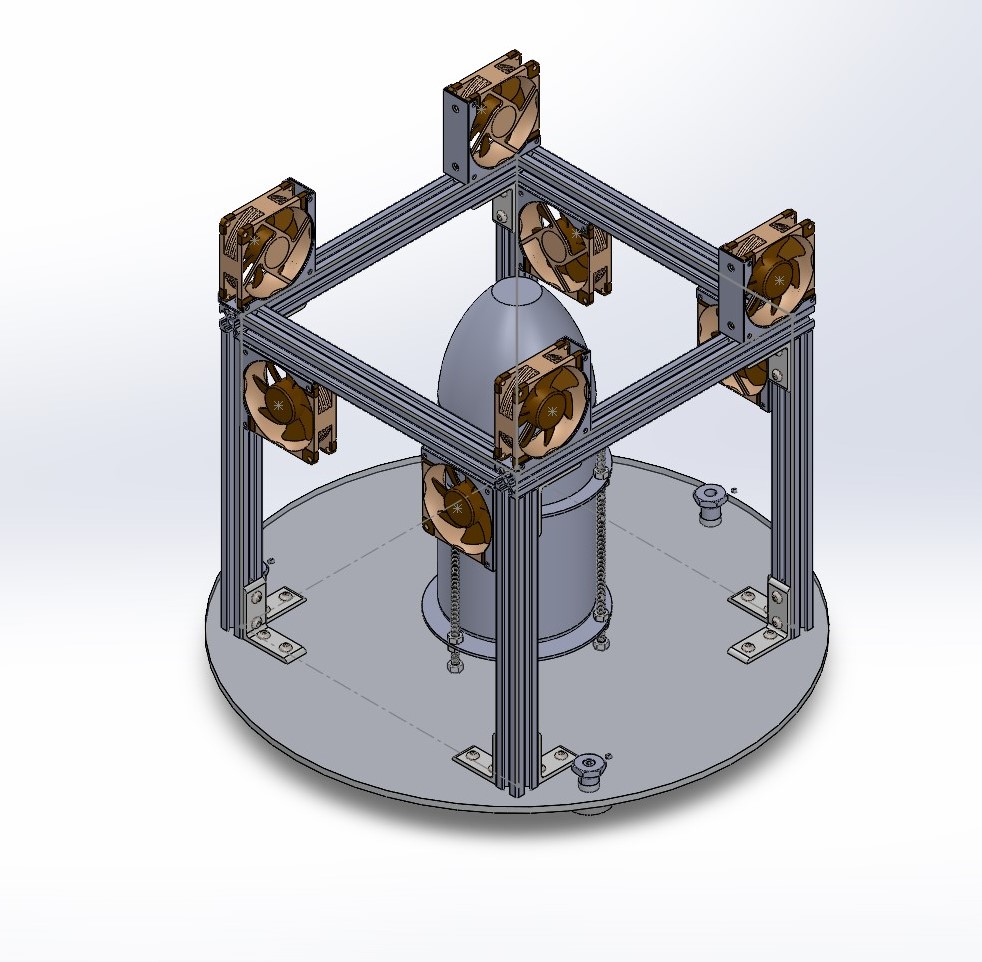
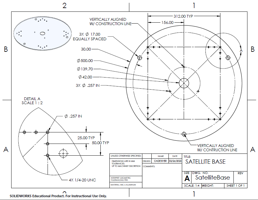
For the manufacturing of the satellite base and frame, I had to communicate with shop staff through parts drawings and files so they could make the satellite base with a high pressure water cutter and frame with a horizontal band saw and tap.
After the design and manufacturing of the satellite, I began testing. Early tests on the flat floor tested the acceleration capabilities of the testbed with full power. The first design with 80mm fans wasn't able to accelerate the testbed sufficiently, so I had two iterations, one with 120mm fans and one with the current fan, which is a NF-A14 industrialPPC-3000 PWM fan from Noctua. The fan has a maximum RPM of 3000 RPM and is controllable through a Pulse Width Modulation (PWM) signal.
Circuit Design and Arduino Development
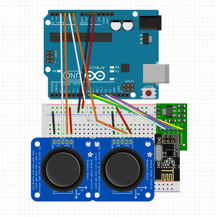
The satellite communicates with the controller via a NRF24L01 radio module. The satellite can be controlled via a joystick or computer commands. Each fan needs its own pulse width modulation (PWM) driver that is controlled with a digital resistor in order to modulate the fan thrust. Because there are 8 fans to control at once, the I2C bus is limited, so I use a multiplexer. Finding a way to reliably drive the fans was an initial challenge, because the fans require a high frequency PWM signal. For the control code, I programmed an Arduino Uno in C/C++ code. Some of the other code on the commanding computer was written in MATLAB.
Control System
One of the first problems in designing a control strategy was allocating a manuever optimally to all of the fans. Because our system is overactuated, there are many different ways in which a combination of the fans can move the satellite to a desired state. This problem was posed as a optmization problem in which the fans are set to a duty cycle that minimizes each fan's deviation from its nominal force value. Because the fans take some time to ramp up, the fans were set to half of their maximum thrust at a nominal state. The optimization problem was formulated as a quadratic program subject to the constraints of each fan providing a force in the x or y direction and moment about the z axis. By assigning a force and moment to the satellite, each fan (indexed) can be assigned a force to accomplish the manuever.
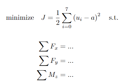
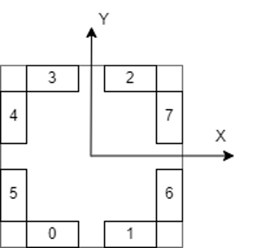
Each fan was labeled so that the optimization problem could be posed. A closed form solution for the force a fan needs to provide was found based on the overall desired force and moment.
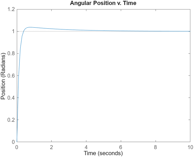
In order to control the satellite, two controllers were developed: a velocity and attitude (angular position) controller. The first controller we tested was the angular position controller, because this could take the place of trimming the fans each experiment if we wanted to go in a straight line. The first control algorithm that I developed was a PD controller. After testing the controller, we observed significant overshoot and oscillation about the setpoint. The designed controller exhibited desired charactertics (see below) so this was unexpected.
The actual response of the controller in an experiment was very different than what was expected from the design. This figure shows that the response oscillated around the setpoint, and wasn't able to settle to the commanded position.
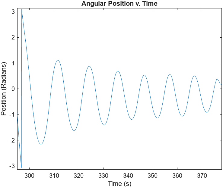
We found this was due to actuator dynamics and pure time delay when commanding the fans. Because of this, we moved to a more sophisticated control strategy, and I began development of an Linear Quadratic Regulator (LQR) controller and Kalman Filter for state estimation, together known as a Linear Quadratic Gaussian (LQG) controller.
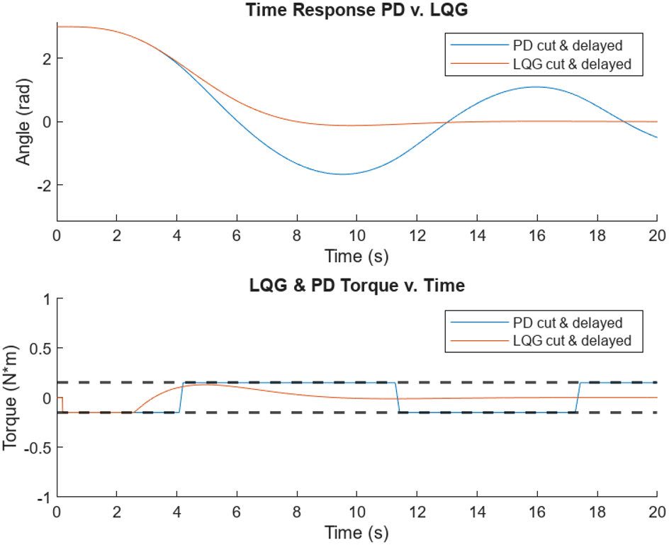
The experimental test of the LQG controller will occur in the next few weeks.
3D Printed Part Fixture
3D Printed Part Fixture
The goal of this project was to make a part fixture to hold a jet engine part while it was in a part test stand. The part fixture was made of a flexible TPU material because it had to fit around the part and hold air as the part was being tested.
The project took many iterations to settle on a material and 3D printer settings that could meet the design requirements.
Python GUI Application
Python GUI Application
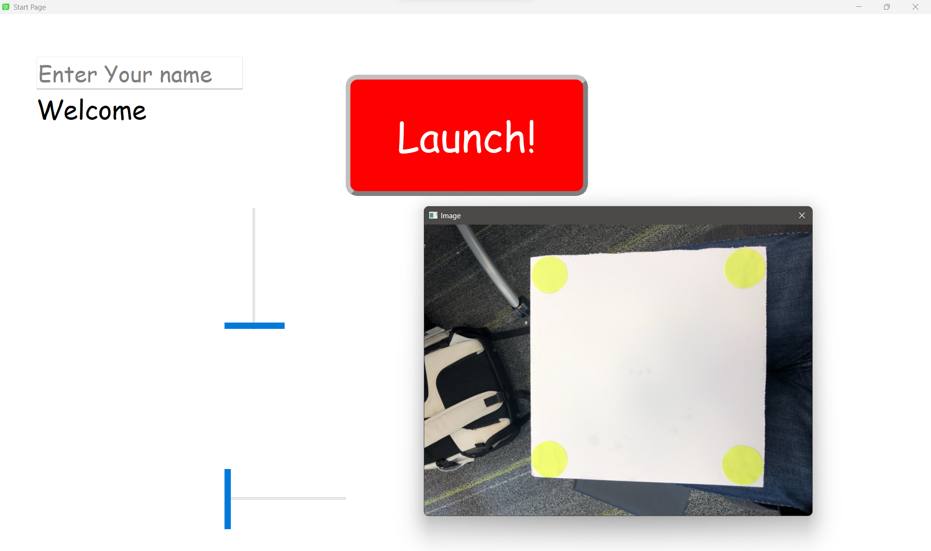
The goal of this project was to develop an application for my First Year Engineering project. Our project was developing a kid's toy for a disabled child. The toy was a ball launcher designed to hit a target. My role was the GUI developer, so I developed an app that could control the toy. The theme of the application was Spiderman. I developed the application in PyQT, a Python binding of the popular GUI toolkit Qt. The project taught me about OOP in Python, and how to organize a larger project.
